Monday, April 10, 2006
Replacing the Maid
There have been many problems concerning maids in Singapore over the years. The news has time and again had reports concerning maid abuse, maids dying because of accidents, and also maids committing crimes themselves. A check on google brings up many articles which are just the tip of the iceberg regarding maid problems in Singapore:
Who’s fault is it when these problems arise – the maid’s or the employer’s? Personally it doesn’t matter. What matters is the concept of employing another human being from a less well-off part of the world to do our menial and sometimes dangerous tasks (like cleaning windows in precarious positions) for us. It is cruel and inhumane but that is a fact of life. However, if robots were to improve the lives of mankind as a whole, then they will definitely have to be able to take on the role of the domestic servant one day.
The Popular Science magazine reports that we are still quite far off from achieving a highly functioning robotic maid, due mostly to the huge problem area of visual perception in robots:
The article also mentions that Sebastian Thrun (http://robots.stanford.edu/) of the Stanford AI Lab (http://ai.stanford.edu/projects.html) has been working on this problem but the dream of fully-autonomous robotic maids still seems quite far off. Extensive research has been carried out by him and his team for many years, with huge amounts of documentation written and many robots made, but at the moment having such a robot is still a wish.
Another point stated in that article is that Radio-Frequency ID (RFID) is the way to go to make robots able to see and interpret things the way humans do. A check with that leading RFID company (http://thingmagic.com/html/about.htm) mentioned shows that the company is mainly focused on developing RFID products. It’s partners (http://thingmagic.com/html/partner.htm) are also not really focused on robotics, but rather on other applications of RFID. It seems that only one leading member of that company has dealt a bit with robots for pipelines (http://thingmagic.com/html/about-mgmt-yaelmaguire.htm).
Nevertheless, the implementation of RFID in the field of robotics is still a relatively new frontier of research and there is growing interest in this area. See the following articles for more information:
Despite all the huge obstacles, the owner of ThingMagic believes that a robotic maid will be possible in 20 years time with the help of RFID technology.
So what exactly is RFID technology?
It is basically an automatic identification method which deals with wireless data transfer between a RFID transceiver (or tag reader) and a RFID tag which is actually a silicon IC chip. This technology is currently fairly widespread, with the ERP gantries & IVUs the most prominent example of this in Singapore. RFID technology is poised to become even more pervasive and powerful, which bodes well for its applications in robotics.
To me, there is one apparent big disadvantage of RFID though: everything that is to be recognised has to be pre-tagged beforehand. I don’t think this counts as true machine vision. But it seems to be one school of thought to deal with the problem of poor visual perception in machines or robots.
Whatever the outcome, I do hope that in 20 years time there will finally be a decent robot to replace the domestic worker, improving the lives of both would-be employer and would-be employee.
Note: The layout seems correct in MS Word and when I click Preview, but on the actual site it's screwed for some reason.
HR6 Humanoid Robot: Your Personal Assistant and Entertainer
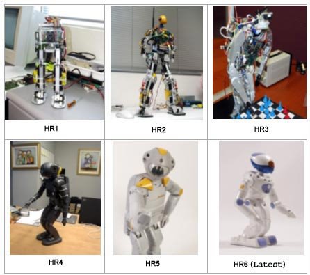 After being used to explore Mars, clean toxic waste and dispose bombs, robots are moving into the home, varying from domestic ones to entertainment ones. These home helpers can be classified in two categories: single-purpose robots with simple designs and cheap prices, such as robotic vacuum cleaners and lawnmowers; and complex, expensive humanoids, which are able to perform several tasks, such as Wakamaru from Mitsubishi, Asimo from Honda and HR6 from Dr Robot, the focus of this blog.
HR6 is an advanced bipedal humanoid robot developed by a Canadian company named Dr Robot. Stands about 52 centimeters tall and weighs 4.8 kilograms, it is the sixth generation of robot prototypes developed for the company's HR Project.
Amazingly, it has a total of 24 degrees of freedom, thus able to walk in a similar way as human beings. In addition to a multitude of sensors, it is also equipped with a color camera, a microphone and stereo audio output. With the equipment, HR6 is able to recognize faces and voices and respond to verbal commands.
Instead of microcontrollers, DSP (Digital Signal Processing) is used in HR6 as DSPs have hardware arithmetic capability that allows real-time execution of algorithms. Freescale Semiconductor's 56F83xx DSP hybrid controller with up to 60 MIPS (Million of Instructions per Second), used in HR6, handles sensing and motion control, taking input from numerous sensors including a bidirectional accelerometer that provides fast response and precise acceleration measurements in the X and Y axes. The use of DSP ensures real-time responses from HR6.
HR6 has many wonderful abilities and can perform many tasks. Some of them are described below.
Bipedal Walking
Each arm and leg of HR6 contains 5 rotational joints while each gripper hand functions with a single joint. There are two more joints enabling the neck and head movement. Thus a total of 24 independent mechanical joints, each driven and controlled by 24 separate motors, provides HR6 with the ability of bipedal walking. With programs written to operate these motors, HR6 can generate numerous gestures and motions, alone or in combination: sit, stand, bend down, walk forward and backward, turn, lie down and even dance. However, it seems that HR6 is unable to climb up and down stairs.
Survival Ability
HR6 is designed to responds to some unplanned events so that it is able to “survival” under some undesirable situation without any human help. If it is knocked over or falls down, it is able to stand up quickly. Similar to modern computer, it is able to shut down to protect itself when its operating temperature exceeds some safe level. It can stop movement to prevent damage to itself or another objects when its movement is hindered. In addition, it knows when and how to recharge itself.
Personal Assistant
HR6 is an excellent personal assistant. It can follow verbal instructions to make appointments and if instructed it will remind the owner later. With connection to the internet, HR6 can check news, weather, gather and store relevant information, which can be retrieved by the owner later. In addition, it can check and read aloud emails. HR6 can replace the remote controls in household and it responds to verbal instructions and can even help the owner to record a program.
The Entertainer
HR6 can play music and sing and dance along with it. It can also take photos and make videos of what it sees. It is able to tell stories while acting them out with some simple movements at the same time. It can be used for video conferencing with connection to the internet. In addition, the owner can access his or her PC via HR6's wireless system.
For more descriptions of HR6's abilities and its detailed specification, please visit http://www.e-clec-tech.com/hr6.html. You can even order one HR6 on the website, provided that you are super rich because the price is not good: $49,999.99. In addition, there are some videos of HR6 there.
In addition, the next generation, HR7, is still under research. According to Dr Robot, HR7 will have five fingers to replace the grippers of the previous generations.
After being used to explore Mars, clean toxic waste and dispose bombs, robots are moving into the home, varying from domestic ones to entertainment ones. These home helpers can be classified in two categories: single-purpose robots with simple designs and cheap prices, such as robotic vacuum cleaners and lawnmowers; and complex, expensive humanoids, which are able to perform several tasks, such as Wakamaru from Mitsubishi, Asimo from Honda and HR6 from Dr Robot, the focus of this blog.
HR6 is an advanced bipedal humanoid robot developed by a Canadian company named Dr Robot. Stands about 52 centimeters tall and weighs 4.8 kilograms, it is the sixth generation of robot prototypes developed for the company's HR Project.
Amazingly, it has a total of 24 degrees of freedom, thus able to walk in a similar way as human beings. In addition to a multitude of sensors, it is also equipped with a color camera, a microphone and stereo audio output. With the equipment, HR6 is able to recognize faces and voices and respond to verbal commands.
Instead of microcontrollers, DSP (Digital Signal Processing) is used in HR6 as DSPs have hardware arithmetic capability that allows real-time execution of algorithms. Freescale Semiconductor's 56F83xx DSP hybrid controller with up to 60 MIPS (Million of Instructions per Second), used in HR6, handles sensing and motion control, taking input from numerous sensors including a bidirectional accelerometer that provides fast response and precise acceleration measurements in the X and Y axes. The use of DSP ensures real-time responses from HR6.
HR6 has many wonderful abilities and can perform many tasks. Some of them are described below.
Bipedal Walking
Each arm and leg of HR6 contains 5 rotational joints while each gripper hand functions with a single joint. There are two more joints enabling the neck and head movement. Thus a total of 24 independent mechanical joints, each driven and controlled by 24 separate motors, provides HR6 with the ability of bipedal walking. With programs written to operate these motors, HR6 can generate numerous gestures and motions, alone or in combination: sit, stand, bend down, walk forward and backward, turn, lie down and even dance. However, it seems that HR6 is unable to climb up and down stairs.
Survival Ability
HR6 is designed to responds to some unplanned events so that it is able to “survival” under some undesirable situation without any human help. If it is knocked over or falls down, it is able to stand up quickly. Similar to modern computer, it is able to shut down to protect itself when its operating temperature exceeds some safe level. It can stop movement to prevent damage to itself or another objects when its movement is hindered. In addition, it knows when and how to recharge itself.
Personal Assistant
HR6 is an excellent personal assistant. It can follow verbal instructions to make appointments and if instructed it will remind the owner later. With connection to the internet, HR6 can check news, weather, gather and store relevant information, which can be retrieved by the owner later. In addition, it can check and read aloud emails. HR6 can replace the remote controls in household and it responds to verbal instructions and can even help the owner to record a program.
The Entertainer
HR6 can play music and sing and dance along with it. It can also take photos and make videos of what it sees. It is able to tell stories while acting them out with some simple movements at the same time. It can be used for video conferencing with connection to the internet. In addition, the owner can access his or her PC via HR6's wireless system.
For more descriptions of HR6's abilities and its detailed specification, please visit http://www.e-clec-tech.com/hr6.html. You can even order one HR6 on the website, provided that you are super rich because the price is not good: $49,999.99. In addition, there are some videos of HR6 there.
In addition, the next generation, HR7, is still under research. According to Dr Robot, HR7 will have five fingers to replace the grippers of the previous generations.
Car-bot, the Grand Challenge
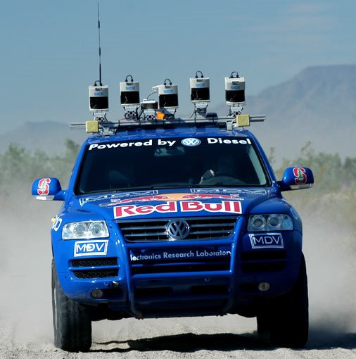 I'm a fan of cars. When I was asked to do a blog on robots, the first thing came to my mind was to look for something to do with cars. I started by looking for “robots+car industry”. It is easy for one to imagine how important robots are to the automotive manufacturing. Indeed, from a source of Robotics Online, 90% of the robots working today are in the factories, and more than half of those are in automotive industry. So cars are built by robots. Then I pondered, is it possible for robot to drive cars. I went to do bit of research; to my surprise, lot of people are concerned about robot driven cars, or more scientifically, autonomous vehicles. Obviously, the people have the greatest interest are the military people, to be precise, U.S. Department of Defense (DoD). Irritated by lost of soldiers due to roadside bombs in Iraq for several years, DoD is particularly keen on autonomous vehicles. As a result, Defense Advanced Research Projects Agency (DARPA) was appointed to do the research so that by 2015, hopefully all the military vehicles in U.S. Army are driverless. The agency took a rather unconventional approach: a public competition with a $1 million prize was held in 2004, namely the Grand Challenge. The idea is to get autonomous vehicles from various research institutions and universities to compete against each other on the 132-mile course in the Mojave Desert. During the course of the competition, the vehicles are not allowed to have any communication with the people. The point of the challenge is however not for military use but to energize the engineering community to tackle the problems need to be solved before vehicles can pilot themselves safely at high speed over unfamiliar terrain.
106 teams took the challenge; none has made to the finishing line. Actually, none has gone beyond 7.4 miles, or 5% of the whole course. However, the competition was nothing close to a failure as objective of the competition was achieved, people were excited about the idea of driverless vehicles, and in the following year, 195 teams responded to the DARPA Grand Challenge 2005. This time, the Agency doubled the prize to 2 million. In the end, 5 teams have finished the 131.6-mile course and “Stanley”, a driverless VW Touareg from Stanford University clinched the championship at a elapsed time of 6 hours, 53 minutes and 58 seconds.
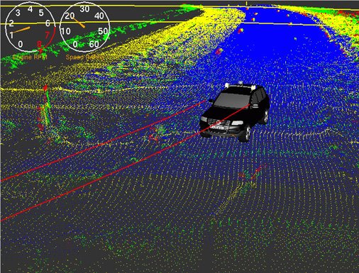
Although one needs only to control steering and throttle to get a car go as he wants, from the incidents of the Grand Challenge, it can be see that the task of driving a motor vehicle is not easy at all. The major difficulty that robots face is the way they see the world. The way they see the world is through measuring, using variety of sensors-laser sensor, cameras, radars, to gauge the shape, dimension, texture of the terrain ahead. They then use the data and process the data to get steering and throttle control in a way that to stay on road and avoid obstacles. Here are some of the techniques that used by various teams.
Laser sensing – The most common sensor are the laser sanners. A beam of light is emitted by the vehicle and bounced off by the terrain ahead. By measuring the time taken for the beam to return, the sensor can calculate the distance to objects and build a 3-D model of the terrain in front of the vehicle. The limitation is that each laser sensor can get only a narrow slice of the world. The detector can’t detect colors and may bounce off shiny surface like a body of water and thus gives a flawed 3-D model.
Video Cameras – video cameras are capable of capturing vast images that extend to a great distance. They can measure the texture and color of the ground, helping the robots understand where is safe to drive and alerts them when there is danger. However, it is difficult to judge the actual size and distance of the objects by using just one camera. They are also of little use during night or in bad weather.
Adaptive Vision – The concept is to get the vehicle run as fast as possible if a smooth road is detected for a distance long enough ahead of the vehicle. This is done by laser range finders to locate a smooth patch of ground and samples the color and texture of this patch by scanning the video image. It then matches the image with the road ahead to look for this color and texture to get a smooth road. If the road changes, the robot slows down until it figures out where is safe to drive.
Radar – Radar sends radio waves to a target and measure the return echo. The advantage of it is that they can see really far into the distance and the radio waves can penetrate dust clouds and bad weather. The downside is that radar beams are not as precise as lasers, resulting in objects that are not obstacles appear, confusing the robot.
Cost Map – This is the programming technique the robots use to find the road and avoid obstacles. The program compiles data from the sensors and divides the world into area that is safe to drive and area that is not safe. A map image is formed with colored area indicating degree of danger of the terrain ahead.
Path Planning – After the cost map is formed, the path planning program is used to find the best path from point to point. The robot figures out every possible path and compares every path on the cost map to find the best path.
Despite the combination of all the sensors used by various teams, unforeseen circumstances can immobilize the vehicle as the car needs to endure the roughness of the world but the sensors are precise instruments that often misled by external interference. The 3rd Grand Challenge is scheduled for 2007 and the racing will be held in the urban environment where the circumstances will get more complicated.
To be honest, I’m not so excited about having cars that can drive by themselves. I like to drive. I’m not trilled by the idea that deprives me of driving. However, the autonomous vehicles do have certain points. Firstly, it can reduce the road accidents, as the robot doesn’t get drowsy or drunk. It is a big deal as we are talking about saving lives. Moreover, precious time is saved as you can now read your emails or newspapers while driving, or better, queuing in traffic jam. Self-driven car is also a blessing to the elderly or the handicapped. They can now move around and have a more sociable life. Thus the autonomous vehicles may have greater social impact than just free people from driving.
To achieve that, lots of things needs to be considered. Apart from driving lessons the robots need to take before they can drive safely, extra attention should be paid when there is people sit inside a robot driven car. This is due to the fact that human bodies are far more fragile than the metallic car bodies. During a sharp brake or turn, the cars don’t feel pain, but people do.
For me, it works when there is a button that can turn the robot off. I can enjoy the fuss free time with the robot taking the wheel during the traffic jam while still be able having fun driving by switched it off.
I'm a fan of cars. When I was asked to do a blog on robots, the first thing came to my mind was to look for something to do with cars. I started by looking for “robots+car industry”. It is easy for one to imagine how important robots are to the automotive manufacturing. Indeed, from a source of Robotics Online, 90% of the robots working today are in the factories, and more than half of those are in automotive industry. So cars are built by robots. Then I pondered, is it possible for robot to drive cars. I went to do bit of research; to my surprise, lot of people are concerned about robot driven cars, or more scientifically, autonomous vehicles. Obviously, the people have the greatest interest are the military people, to be precise, U.S. Department of Defense (DoD). Irritated by lost of soldiers due to roadside bombs in Iraq for several years, DoD is particularly keen on autonomous vehicles. As a result, Defense Advanced Research Projects Agency (DARPA) was appointed to do the research so that by 2015, hopefully all the military vehicles in U.S. Army are driverless. The agency took a rather unconventional approach: a public competition with a $1 million prize was held in 2004, namely the Grand Challenge. The idea is to get autonomous vehicles from various research institutions and universities to compete against each other on the 132-mile course in the Mojave Desert. During the course of the competition, the vehicles are not allowed to have any communication with the people. The point of the challenge is however not for military use but to energize the engineering community to tackle the problems need to be solved before vehicles can pilot themselves safely at high speed over unfamiliar terrain.
106 teams took the challenge; none has made to the finishing line. Actually, none has gone beyond 7.4 miles, or 5% of the whole course. However, the competition was nothing close to a failure as objective of the competition was achieved, people were excited about the idea of driverless vehicles, and in the following year, 195 teams responded to the DARPA Grand Challenge 2005. This time, the Agency doubled the prize to 2 million. In the end, 5 teams have finished the 131.6-mile course and “Stanley”, a driverless VW Touareg from Stanford University clinched the championship at a elapsed time of 6 hours, 53 minutes and 58 seconds.
Although one needs only to control steering and throttle to get a car go as he wants, from the incidents of the Grand Challenge, it can be see that the task of driving a motor vehicle is not easy at all. The major difficulty that robots face is the way they see the world. The way they see the world is through measuring, using variety of sensors-laser sensor, cameras, radars, to gauge the shape, dimension, texture of the terrain ahead. They then use the data and process the data to get steering and throttle control in a way that to stay on road and avoid obstacles. Here are some of the techniques that used by various teams.
Laser sensing – The most common sensor are the laser sanners. A beam of light is emitted by the vehicle and bounced off by the terrain ahead. By measuring the time taken for the beam to return, the sensor can calculate the distance to objects and build a 3-D model of the terrain in front of the vehicle. The limitation is that each laser sensor can get only a narrow slice of the world. The detector can’t detect colors and may bounce off shiny surface like a body of water and thus gives a flawed 3-D model.
Video Cameras – video cameras are capable of capturing vast images that extend to a great distance. They can measure the texture and color of the ground, helping the robots understand where is safe to drive and alerts them when there is danger. However, it is difficult to judge the actual size and distance of the objects by using just one camera. They are also of little use during night or in bad weather.
Adaptive Vision – The concept is to get the vehicle run as fast as possible if a smooth road is detected for a distance long enough ahead of the vehicle. This is done by laser range finders to locate a smooth patch of ground and samples the color and texture of this patch by scanning the video image. It then matches the image with the road ahead to look for this color and texture to get a smooth road. If the road changes, the robot slows down until it figures out where is safe to drive.
Radar – Radar sends radio waves to a target and measure the return echo. The advantage of it is that they can see really far into the distance and the radio waves can penetrate dust clouds and bad weather. The downside is that radar beams are not as precise as lasers, resulting in objects that are not obstacles appear, confusing the robot.
Cost Map – This is the programming technique the robots use to find the road and avoid obstacles. The program compiles data from the sensors and divides the world into area that is safe to drive and area that is not safe. A map image is formed with colored area indicating degree of danger of the terrain ahead.
Path Planning – After the cost map is formed, the path planning program is used to find the best path from point to point. The robot figures out every possible path and compares every path on the cost map to find the best path.
Despite the combination of all the sensors used by various teams, unforeseen circumstances can immobilize the vehicle as the car needs to endure the roughness of the world but the sensors are precise instruments that often misled by external interference. The 3rd Grand Challenge is scheduled for 2007 and the racing will be held in the urban environment where the circumstances will get more complicated.
To be honest, I’m not so excited about having cars that can drive by themselves. I like to drive. I’m not trilled by the idea that deprives me of driving. However, the autonomous vehicles do have certain points. Firstly, it can reduce the road accidents, as the robot doesn’t get drowsy or drunk. It is a big deal as we are talking about saving lives. Moreover, precious time is saved as you can now read your emails or newspapers while driving, or better, queuing in traffic jam. Self-driven car is also a blessing to the elderly or the handicapped. They can now move around and have a more sociable life. Thus the autonomous vehicles may have greater social impact than just free people from driving.
To achieve that, lots of things needs to be considered. Apart from driving lessons the robots need to take before they can drive safely, extra attention should be paid when there is people sit inside a robot driven car. This is due to the fact that human bodies are far more fragile than the metallic car bodies. During a sharp brake or turn, the cars don’t feel pain, but people do.
For me, it works when there is a button that can turn the robot off. I can enjoy the fuss free time with the robot taking the wheel during the traffic jam while still be able having fun driving by switched it off.
Cool Robot designed for deployment in Antarctica
Researchers from the Thayer School of Engineering at Dartmouth College have built a robot designed to do research in Antarctica.
The Environment:
The weather conditions are low snowfall, moderate winds, and extreme cold. The land is mostly plain aside from dune like features called Sastrugi. They are identifiable on satellite imagery. The snow is mostly firm , but also includes a few softer drifts. It also is capable of sustaining mobility in wind and able to operate at temperatures as low as -40°C.
The mission will include the robot being transported in an aircraft and dropped of at a certain location. The robot will then be required to travel over 500km in 2weeks to the target location where it can spend a 2-3 months looking data before returning to the base.
Keeping all these considerations in mind the team came up with the following design specifications:
Max. Speed > 0.80 m/s
Empty mass <> 15 kg
Ground Pressure  16x6-8 ATV tire are used as they are low mass and have good traction.the hubs for the tires were custom designed to meet the weight requirements. The custom wheels and hubs were designed to sustain the roughly 220N static load and 880 N dynamic load per wheel.
4 four EAD brushless DC motors combined with 90% efficient, 100:1 gear ratio planetary gearboxes were used. The gearboces were lubricated for -50°C operation. They provided continuous torque of roughly 8 N-m at each wheel.
Power:
Travel of 500 km in two weeks requires an average speed of 0.41 m/s.Average power required is 90 W. the robot also has a top speed of 8m/s requiring 180W. 40 W for housekeeping power, internal drivetrain resistance, and power system efficiencies is needed, this makes the total power needed about 250 W. The Antarctic is well suited for Solar powered vehicles. The plateau receives 224 hours sunlight and is subject to little precipitation and fog.
A dedicated 8-bit microcontroller coordinates the power system. The goal of the control scheme is to match the available power from the boost converters to the instantaneous demand of the motors and housekeeping.
Navigation and Control:
The path is generally plain and so a “Mixed Mode” operation which is based on human behavior for e.g. hiking a known path over a long distance. A local mode is also included so that the robot may react to unexpected situations.
16x6-8 ATV tire are used as they are low mass and have good traction.the hubs for the tires were custom designed to meet the weight requirements. The custom wheels and hubs were designed to sustain the roughly 220N static load and 880 N dynamic load per wheel.
4 four EAD brushless DC motors combined with 90% efficient, 100:1 gear ratio planetary gearboxes were used. The gearboces were lubricated for -50°C operation. They provided continuous torque of roughly 8 N-m at each wheel.
Power:
Travel of 500 km in two weeks requires an average speed of 0.41 m/s.Average power required is 90 W. the robot also has a top speed of 8m/s requiring 180W. 40 W for housekeeping power, internal drivetrain resistance, and power system efficiencies is needed, this makes the total power needed about 250 W. The Antarctic is well suited for Solar powered vehicles. The plateau receives 224 hours sunlight and is subject to little precipitation and fog.
A dedicated 8-bit microcontroller coordinates the power system. The goal of the control scheme is to match the available power from the boost converters to the instantaneous demand of the motors and housekeeping.
Navigation and Control:
The path is generally plain and so a “Mixed Mode” operation which is based on human behavior for e.g. hiking a known path over a long distance. A local mode is also included so that the robot may react to unexpected situations.
 The robot’s microcontroller will communicate with a base station or through the Iridium Satellite System, which provides complete coverage of the Polar Regions.It allows operators to query robot status and send new target and waypoint data to the
robot, as well as allowing the robot to send warnings to the base station when it detects a potentially dangerous situation.
Four motor controllers provide closed-loop wheel speed control. While the motor controllers can also be set to torque control mode, leaving them in velocity control mode allows more sophisticated traction control through the master microcontroller. The master microcontroller has access to the four motor currents and encoded wheel speeds. The master microcontroller also handles navigation, sensor monitoring, GPS and communication.
Results:
The Robot was tested in Greenland which has similar conditions and will soon be tested in Antarctica itself. NASA is interested in testing the robot for its cost effective design to look for bacteria in Antarctica. Other potential missions include deploying arrays of magnetometers, seismometers, radio receivers and meteorological instruments, measuring ionosphere disturbances through synchronization of GPS signals, using ground-penetrating radar (GPR) to survey crevasse-free routes for field parties or traverse teams, and conducting glaciological surveys with GPR. Robot arrays could also provide high-bandwidth communications links and mobile power systems for field scientists.
The robot’s microcontroller will communicate with a base station or through the Iridium Satellite System, which provides complete coverage of the Polar Regions.It allows operators to query robot status and send new target and waypoint data to the
robot, as well as allowing the robot to send warnings to the base station when it detects a potentially dangerous situation.
Four motor controllers provide closed-loop wheel speed control. While the motor controllers can also be set to torque control mode, leaving them in velocity control mode allows more sophisticated traction control through the master microcontroller. The master microcontroller has access to the four motor currents and encoded wheel speeds. The master microcontroller also handles navigation, sensor monitoring, GPS and communication.
Results:
The Robot was tested in Greenland which has similar conditions and will soon be tested in Antarctica itself. NASA is interested in testing the robot for its cost effective design to look for bacteria in Antarctica. Other potential missions include deploying arrays of magnetometers, seismometers, radio receivers and meteorological instruments, measuring ionosphere disturbances through synchronization of GPS signals, using ground-penetrating radar (GPR) to survey crevasse-free routes for field parties or traverse teams, and conducting glaciological surveys with GPR. Robot arrays could also provide high-bandwidth communications links and mobile power systems for field scientists.
 16x6-8 ATV tire are used as they are low mass and have good traction.the hubs for the tires were custom designed to meet the weight requirements. The custom wheels and hubs were designed to sustain the roughly 220N static load and 880 N dynamic load per wheel.
4 four EAD brushless DC motors combined with 90% efficient, 100:1 gear ratio planetary gearboxes were used. The gearboces were lubricated for -50°C operation. They provided continuous torque of roughly 8 N-m at each wheel.
Power:
Travel of 500 km in two weeks requires an average speed of 0.41 m/s.Average power required is 90 W. the robot also has a top speed of 8m/s requiring 180W. 40 W for housekeeping power, internal drivetrain resistance, and power system efficiencies is needed, this makes the total power needed about 250 W. The Antarctic is well suited for Solar powered vehicles. The plateau receives 224 hours sunlight and is subject to little precipitation and fog.
A dedicated 8-bit microcontroller coordinates the power system. The goal of the control scheme is to match the available power from the boost converters to the instantaneous demand of the motors and housekeeping.
Navigation and Control:
The path is generally plain and so a “Mixed Mode” operation which is based on human behavior for e.g. hiking a known path over a long distance. A local mode is also included so that the robot may react to unexpected situations.
The robot’s microcontroller will communicate with a base station or through the Iridium Satellite System, which provides complete coverage of the Polar Regions.It allows operators to query robot status and send new target and waypoint data to the
robot, as well as allowing the robot to send warnings to the base station when it detects a potentially dangerous situation.
Four motor controllers provide closed-loop wheel speed control. While the motor controllers can also be set to torque control mode, leaving them in velocity control mode allows more sophisticated traction control through the master microcontroller. The master microcontroller has access to the four motor currents and encoded wheel speeds. The master microcontroller also handles navigation, sensor monitoring, GPS and communication.
Results:
The Robot was tested in Greenland which has similar conditions and will soon be tested in Antarctica itself. NASA is interested in testing the robot for its cost effective design to look for bacteria in Antarctica. Other potential missions include deploying arrays of magnetometers, seismometers, radio receivers and meteorological instruments, measuring ionosphere disturbances through synchronization of GPS signals, using ground-penetrating radar (GPR) to survey crevasse-free routes for field parties or traverse teams, and conducting glaciological surveys with GPR. Robot arrays could also provide high-bandwidth communications links and mobile power systems for field scientists.
16x6-8 ATV tire are used as they are low mass and have good traction.the hubs for the tires were custom designed to meet the weight requirements. The custom wheels and hubs were designed to sustain the roughly 220N static load and 880 N dynamic load per wheel.
4 four EAD brushless DC motors combined with 90% efficient, 100:1 gear ratio planetary gearboxes were used. The gearboces were lubricated for -50°C operation. They provided continuous torque of roughly 8 N-m at each wheel.
Power:
Travel of 500 km in two weeks requires an average speed of 0.41 m/s.Average power required is 90 W. the robot also has a top speed of 8m/s requiring 180W. 40 W for housekeeping power, internal drivetrain resistance, and power system efficiencies is needed, this makes the total power needed about 250 W. The Antarctic is well suited for Solar powered vehicles. The plateau receives 224 hours sunlight and is subject to little precipitation and fog.
A dedicated 8-bit microcontroller coordinates the power system. The goal of the control scheme is to match the available power from the boost converters to the instantaneous demand of the motors and housekeeping.
Navigation and Control:
The path is generally plain and so a “Mixed Mode” operation which is based on human behavior for e.g. hiking a known path over a long distance. A local mode is also included so that the robot may react to unexpected situations.
The robot’s microcontroller will communicate with a base station or through the Iridium Satellite System, which provides complete coverage of the Polar Regions.It allows operators to query robot status and send new target and waypoint data to the
robot, as well as allowing the robot to send warnings to the base station when it detects a potentially dangerous situation.
Four motor controllers provide closed-loop wheel speed control. While the motor controllers can also be set to torque control mode, leaving them in velocity control mode allows more sophisticated traction control through the master microcontroller. The master microcontroller has access to the four motor currents and encoded wheel speeds. The master microcontroller also handles navigation, sensor monitoring, GPS and communication.
Results:
The Robot was tested in Greenland which has similar conditions and will soon be tested in Antarctica itself. NASA is interested in testing the robot for its cost effective design to look for bacteria in Antarctica. Other potential missions include deploying arrays of magnetometers, seismometers, radio receivers and meteorological instruments, measuring ionosphere disturbances through synchronization of GPS signals, using ground-penetrating radar (GPR) to survey crevasse-free routes for field parties or traverse teams, and conducting glaciological surveys with GPR. Robot arrays could also provide high-bandwidth communications links and mobile power systems for field scientists.
Sunday, April 09, 2006
HONDA ASIMO - the future
After motocycles, cars and power products, Honda has taken up a new challenge in mobility – the development of a two-legged humanoid robot that can walk. The aim of the function for the robot in the human living space was to create a partner for people, a social robot. From this challenge came the HONDA ASIMO, Advanced Step in Innovative Mobility. ASIMO is designed to operate in the real world with its abilities to walk smoothly, climb stairs and recognise people's voices.
The ASIMO is scheduled for use in a pedestrian safety program named “Step to Safety with ASIMO”. This is a program where ASIMO will help students learn the safe and responsible steps to road-crossing using its human-like capabilities. Using ASMIO in this program is beneficial as such a robot will catch the attention of the young children and allow them to pay more attention to the safety steps being taught.
Besides this, ASIMO has been involved in many entertainment events such as performing for visitors at Aquarium of the Pacific, dancing with the host on the Ellen DeGeneres show and even walking down the red carpet for the premiere of the movie, “Robots”. The interactive nature of this robot has endeared itself to viewers from all over the world.
Videos of ASIMO in action can be viewed on the website at this link "http://asimo.honda.com/inside_asimo_movies.asp". It is fascinating how the movement of the ASIMO is so human-like, from the dipping of the shoulders to the turning of the hips when running. Look out for the particular video "NEW MOBILITY". You will be amazed by the human-like manner in which the robot comes to a stop after running. You can't help but be reminded of a human runner after you watch that clip.
Honda engineers created ASIMO with 26 degrees of freedom to allow it to mimic human movement as much as possible. For the technical part, we shall concentrate on the movement component.This robot’s walk is modeled after a human being with the human skeleton used for reference when locating the leg joints. The joint movement was calibrated after research carried out on human walking on flat ground and stairs. From there, the centre of gravity of each leg was modeled after that of the human body. Similarly, to obtain the idea torque exerted on the joints during motion, vectors at the joints during human motion were measured.
Besides this, sensors were also implemented. These were based on the 3 senses of balance that humans have, namely speed by the otolith of the inner ear, angular speed by the semicircular canals and deep sensations from the muscles and skin, which sense the operating angle of the joints, angular speed, muscle power, pressure on the soles of the feet and skin sensations. From this, the robot was equipped with a joint angle sensor, a 6-axis force sensor and a speed sensor with gyroscope to determine position.
To achieve stable walking, three main posture controls are used, namely floor reaction control which maintains firm standing control of the soles of the feet even during floor unevenness, target ZMP (Zero Moment Point where inertial force is 0) control which is the control to maintain position by accelerating the upper torso in the direction in which it threatens to fall and finally, foot planting location control which is the control using side steps to adjust for irregularities in the upper torso caused by the abovementioned target ZMP control.
Finally, a new two-legged walking technique allowed for more flexible walking by creating prediction movement control. For example, when humans wish to turn a corner, they will shift their centre of gravity towards the inside of the turn. With the Intelligent Walking Technology, ASIMO is able to predict its next movement in real time and adjust its centre of gravity correspondingly in preparation for any turns.
Reference: http://asimo.honda.com/inside_asimo.asp?bhcp=1
Pictures can be found at http://asimo.honda.com/photo_viewer_news.asp
Surgical Robotic systems

Robots utilized in medicine, especially in surgeries, serve as assistance to doctors in their role of dispensing medical treatment to patients and even enhance their services. An important aspect is the improvement of the surgeon’s dexterity during surgery. No matter how skilled a surgeon is, there is always a slight tremor of the hands. Morever, operations of highly sensitive and confined body spaces like the brain, heart and prostate, can be performed by only a limited number of surgeons who are skilled and experienced enough for the task. With the advent of such assistive robotic surgical systems as the Automated Endoscopic System for Optimal positioning (AESOP), the Da Vinci surgical system and the ZEUS robotic system, hand tremors are a thing of the past.
The robotic limbs, holding onto the surgical instruments, could execute movements that are as minute as a millionth of an inch. The march towards non-invasive surgery motivates the development of such systems. Increasing number of heart by-pass surgeries are now performed through pin-hole incisions, via a robot-assisted endoscopic extensions. The four-arm Da Vinci system offers great precision and eliminates the need for inverted manipulation of the surgical instruments as the on-board processor can translate the surgeon’s hand movements correctly into the desired manipulation of the surgical instruments. There is also three-dimensional imaging capability via a camera attached to one of the arms.
At the Medical Centre of Hershey, Dr Ralph J. Damiano Jr., used a surgical robotic system that has a camera that magnify views of operation procedures by a power of 16.
Voice commands-driven robots are also a possibility in another up-coming system, called “Hermes”. This will the advent of the “intelligent” operating theatre, in which the doctor just focus on making critical surgical decisions and “asks” the robot to execute the moves.

In use at 280 hospitals now is the AESOP system.
Using the Zeus or da Vinci system, largely invasive surgeries such as heart bypasses, can be made less painful and complicated. Traditional techniques of making a 1-foot-long incision on the chest and thereafter prying open the rib cage to reveal the heart is now replaced by cutting just a tiny hole of 1 cm through which endoscopic extensions containing fibre optics and surgical tools are inserted.
References:
How robotics will work, http://electronics.howstuffworks.com/robotic-surgery1.htm
Robotic Surgery, http://ipp.nasa.gov/innovation/Innovation52/robsurg.htm
Laproscopic Surgery, http://www.lapsurgery.com/robotics.htm#ROBOTS%20IN%20LAPAROSCOPIC%20INGUINAL%20HERNIA%20REPAIR
In Vivo Robots for Remote surgery
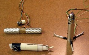
A team of researchers from the University of Nebraska-Lincoln and University of Nebraska Medical Center had recently came up with small robots that could have the potential to revolutionize the way minimally invasive surgery (MIS) is performed. Some of the early prototypes used for testing are shown in the figure below. These medical responders of the future will be at most the size of a lipstick and can be driven remotely around inside the human body to perform tasks like stopping internal bleeding by clamping, clotting or cauterizing wounds. These will be the first robots that actually work from inside the body.
Conventionally, to perform similar operations, one of the surgical techniques used is laparoscopic. In this technique, a small incision is made and a camera is inserted through this incision to provide visual feedback of the operative field. To manipulate the tissues, another long instruments with surgical tools attached to the tip are then inserted through the opening. The benefits of such operations are that there will be minimum operative blood loss and post operative pain. Due to the small incision made for the operation, the recovery time is also shorter.
However, the benefits of laparoscopy are limited to less complex procedures. This is because of the reduced access of such a surgery. Reduced access reduces dexterity, limits perception, increases strain and the likelihood of error, and lengthens procedure times. The operative field is visualized through an electronic interface, and tissue manipulation is performed with long instruments that impose severe ergonomic limitations. The long, rigid instruments and cameras typically used in laparoscopic surgery are constrained to only four degrees of freedom (three rotations and in-out translation) through the entry incision. This prevents the ability to orient the tool tips arbitrarily. Dexterity is significantly reduced because of the lost degrees of freedom and because of motion reversal due to the fulcrum effect at the entry point. Therefore there are limitations on the amount of dexterity and visualization a surgeon has for more complex operations.
To overcome the limitations of dexterity and visualization of laparoscopy, the robots invented by the researchers are small, about 3 inches tall, and are wheeled. They can be inserted totally through standard laparoscopic ports into the body and controlled by surgeons in different locations through computer. Each of the robots will be fitted with a certain tool for carrying out a certain function. For example one such robot maybe fitted with cameras and lights to provide pictures of the operative field to the surgeons while others may be equipped with surgical tools for making incisions or to deliver medicine depending on the tasks. “These remotely controlled in vivo robots provide the surgeon with an enhanced field of view from arbitrary angles, as well as provide dexterous manipulators not constrained by small incisions in the abdominal wall,” Dr. Oleynikov, M.D., director of education and training for the minimally invasive and computer-assisted surgery initiative.
Tests conducted on animals have shown very positive results and performances. Although still in the testing stage, the implication of such an application is far reaching. NASA already has plan to use such a system for its future space mission to attend to astronaut that needs medical attention in space. These robots also have potential use in the battle field where surgeon could remotely help to treat soldiers at the front line.
"All eyes on the line"
Industrial robots have evolved considerably since an invention by Joseph Engelberger and George Devol called “Unimate” was installed at a General Motors plant to extract moulded parts from die-casting machines in the late 1950s. Robots today have evolved to the point where they can be used for a variety of tasks with just a change of the tools and the programming. Their precision and accuracy have improved by leaps and bounds, as has the software that powers them, making these automation tools capable of handling tasks as varied as grasping and placing an auto windshield to selecting only perfectly formed cookies for packaging. Industrial robots are cropping up in almost every factory setting, being used for packaging, assembling, palletizing, dispensing etc.

Previous posts have given a deeper insight into the working of robotic arms. But, how do these robots gather accurate information to accomplish a task without error? In the industrial setting, parts and components must be locked into precisely fixed positions for "blind" robotics systems (consisting of the robot and a computer-driven controller) to function. To ensure such consistency and reliability in industrial processes would mean high-cost, custom-engineered and low-tolerance fixed manufacturing lines. Here, a development contributing to the smooth, flexible working of industrial robots is examined, that is the addition of a machine vision system to these robots. This system enables robots to adapt to changing conditions and variability in the production environment.
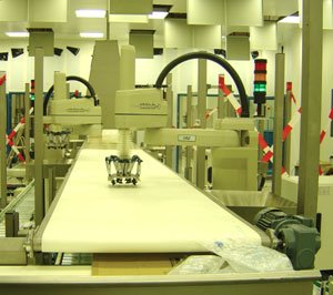
ABB U.S. partnered with Braintech Inc. in North Vancouver, British Columbia, to create a commercial out-of-the-box vision-enabled robotic system, called TrueVie w. The system consists of
1. An ABB robot (as shown in the figure on the right)
2. An ABB controller
3. Braintech's eVisionFactory (eVF) software
4. A computer running Windows
5. A standard CCD camera
6. An integrated lighting system to ensure the camera can capture clear images
7. An end-effector (i.e. a robot "hand")
8. Conveyors
w. The system consists of
1. An ABB robot (as shown in the figure on the right)
2. An ABB controller
3. Braintech's eVisionFactory (eVF) software
4. A computer running Windows
5. A standard CCD camera
6. An integrated lighting system to ensure the camera can capture clear images
7. An end-effector (i.e. a robot "hand")
8. ConveyorsTrueView, combining ABB robots and Braintech’s eVF software has helped liberate manufacturing industries from the limitations of fixed automation. The system functions as described below.
- A 3-D camera, which is integrated into the robot’s end-effector captures an image of an object as it moves along the conveyor, and transmits that image via an Ethernet network to the Windows-based PC.
- The eVF software on the PC analyzes the image to find identifiable features in the object.
- The software uses that information to calculate where the object sits in 3-D space (it defines the x, y, z position, and roll, pitch, and yaw angles) and transmits that coordinate data back to the robot, so the robot hand can intercept each part correctly for grasping or performing other processes, with accuracy to within one tenth of a millimetre!
The TrueView system can link up to five robots under one controller. It can see the differences among several different parts and perform multiple actions as circumstances might require.
In a nut-shell, the success of robotic arms (however flexible and evolutionary they may be) is primarily attributed to the competency and robustness of their computerized control systems. The arms themselves are mere puppets swaying to the tune of the controller...
References:
Conversational Humanoid
Humanoids are one of the fast developing areas in the robotics. Many research institutes and companies are doing researches in areas such as human-robot interactions, biomimetics and so on. Companies such as Honda, Sony together with leading institutions in Japan and US developed many interesting humanoid technologies. One such example is the conversational humanoid from MIT Media Lab.
They are developing autonomous agents that are capable of having a real-time face-to-face conversation with a human. These agents are human in form and communicate using both verbal and non-verbal modalities. We believe that such agents provide a new form of human-computer interface which users can interact with naturally, without training, since they already know how to engage in face-to-face conversation with other people. In addition to providing a platform for evaluating theories of human communicative behavior, these agents can be used in applications from virtual salespeople and support personnel to virtual playmates for children.
Their first generation humanoid system was Animated Conversation, where two autonomous humanoid animated characters carried on a conversation. While there was no human participant in these dialogues, Animated Conversation was the first system to automatically generate verbal and non-verbal communicative behaviors such as hand gestures, facial displays, intonation and speech.
The second generation humanoid was Gandalf, an animated cartoon face on a screen that could answer spoken questions about the solar system. Gandalf could sense the user's motion by having the user wear an electro-magnetic tracking system, and thus could respond to non-verbal behavior as well as verbal behavior. Although Gandalf operated in real-time, his outputs were simply selected from a library of stock responses.
The next generation has a fully articulated body and senses the user passively through cameras. The agent, named Rea (for Real Estate Agent), plays the role of a real estate salesperson who interacts with users to determine their needs, shows them around virtual properties, and attempts to sell them a house. We selected real estate sales as our application area, since there are opportunities for both task-oriented and socially-oriented conversation. As opposed to Gandalf, Rea actually synthesizes her responses--including speech and accompanying hand gestures--based on a grammar and lexicon and communicative context.
Their challenges comprise creating a synthetic human is a large undertaking that introduces a wide range of hard research issues. Current research directions we are pursuing include the recognition of classes of user conversational hand gestures, the synthesis of Rea's hand gestures based on a more detailed understanding of pragmatic information, and the planning of mixed-initiative dialog including non-task-oriented 'small talk' and conversational storytelling. The research version of Rea runs on a collection of five SGIs and PCs. A German version of Rea has also been developed and we are currently working on a PC-based application of the technology in which the agent plays the role of a child's virtual playmate.
Their team involves Justine Cassell, Tim Bickmore, Lee Campbell, Hannes Vilhjálmsson,and Hao Yan from MIT Media Lab.
Reference: http://www.media.mit.edu/gnl/projects/humanoid/
Microbots: Micro Life-savers.
Microbots: Micro Life-savers.
Introduction
Rapid advancement in nanotechnology has now allowed the production of smaller and smaller robots. Prototypes of robots, which measure only a few micrometers across, are already being made, and it is only a method of time before, it would be mass-produced. Kazushi Ishiyama, from the
 Kazushi Ishiyama
Drug delivery:
The main drawback of conventional drug delivery methods is the difficulty in delivering the exact dosage of drugs to the precise target. The digestive system of the patient breaks down a large portion of the drug, before it could reach its intended target. One method of bypassing this problem is to take larger doses of medications. However, overdosing usually carries harmful side-effects and might even be lethal. Although injections do not have this problem, they are expensive and are difficult to self-administer. Microbots provide an elegant solution to this problem.
A microbot could be injected directly into the bloodstream of the patient, where it can be used to deliver required level of medications directly to malignant cells (where it is needed) at regular intervals. Thus there is no longer any problem of taking in too large or too small of a dose of medications, and there is no longer any need for a trained medical professional to be around, each time the patient requires a dose of medication.
Destroying cancerous cells
The conventional method of cancer treatment involves zapping cancerous cells with radiotherapy. While it is effective in eliminating the cancerous cells, the healthy cells around cancerous cells are often killed in the process, thereby weakening the immune system of the patient. However, microbot can be used to eliminate the cancerous cells, without harming the healthy cells around them. Kazushi Ishiyama’s microbot prototype is a rotating magnetized screw, which can be used to as a form of cancer treatment. The microbot is first injected into the patient, where it will burrow straight into the cancerous cells and unleash a hot metal spike to destroy them.
Technology behind the Microbot
The microbot is based of cylindrical magnets and is shaped like a small screw. The microbot is controlled by applying a three-dimensional electro-magnetic field, which will control the spin and direction of the microbot. Due to its small size, the microbot does not carry with it its own power unit, instead it is powered by the electro-magnetic field. By varying the pulses of the magnetic field, the temperature of the microbot could be increased, such that it is hot enough to burn away cancerous tissue. The microbot is strong enough to burrow through a 2cm thick steak in just 20 seconds.
Drawbacks
While the microbot is small in size, it might still be fatal if it accidentally blocks a blood vessel. Thus doctors are still apprehensive about testing the prototype on humans. Because lives are at stake, medical robotics usually requires an exceptionally stable control system. Thus there is a need to have a stable control system, such that the microbot will almost never stray into blood vessels. Another solution would be to further reduce the size of the microbot, until the extent that it will not block a blood vessel even if it accidentally strays into one.
Given enough time, I am sure that these problems would be overcome and we will see microbots being used to save countless lives.
Reference
http://news.bbc.co.uk/1/hi/health/1386440.stm
http://www.dietarysupplementnews.com/archives2001.htm
http://server.admin.state.mn.us/issues/scan.htm?Id=1355
http://www.pathfinder.com/asiaweek/magazine/2001/0803/pioneer3.html
Saturday, April 08, 2006
Robotic Probe of the Great Pyramid of Egypt
The Great Pyramid of Egypt has always fascinated people because of its ancient mysteries and secrets, which only a few have been discovered. One of the Pyramids, named Khufu Pyramid, is particularly fascinating due to its highly complex interior, which contains countless secret chambers that researchers have yet to discover. In 2003, National Geographic, using the same kind of robot used to search for survivors in the ruins of the World Trade Center, tried to solve a mystery that lies deep in the bowels of the 4,500-year-old Great Pyramid of Giza. Inside the Khufu Pyramid lies one main chamber called the Queen’s Chamber, in which a tiny square tunnel leading to a stone hatch with copper handles was discovered in 1872. No one knows the purpose of the shaft, and no one knows what lies behind the hatch. In addition to that, many air shafts inside the chamber have been discovered but the functions of these shafts were not clear.
The square shaft begins with a "tank trap" or initial dip and appears to end 16.5 meters (54 feet) short of the outer side of the pyramid's surface at the miniature door (shown by the figure below). The door itself is only 8 cm (3.25 inches) thick and seals the end of the narrow shaft. National Geographic designed a robot called “Pyramid Rover” to go up the shaft and find out what lies behind the copper handles at the end of the tunnel. The total length of the shaft is 208 feet or approximately 61 meter and is inclined at 40 degree angle.
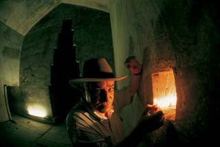 The Technology behind Pyramid Rover
The Pyramid Rover, whose prototype was designed by a German scientist Rudolf Gantenbrink, is equipped with a laser guidance system and a SONY CCD miniature video with pan and tilt capabilities. The structural parts are made of aircraft aluminum and seven independent electric motors with precision gears drive up the upper and lower wheel, providing leverage thrust of 20 kg and pulling power of 40 kg under ideal traction conditions. The CCD video is connected to the monitoring circuit outside the tunnel.
Since no one has explored the square tunnel before, obstacles such as boulders and unanticipated traps were expected. Therefore, Pyramid Rover is built based on information-based criterion to determine the “path strategy” of a robot. The criterion determines the next best path for a robot taking into account the distance traveled to reach a position, obstacle avoidance strategy, and pre-programmed algorithm about the terrain (in this case the square tunnel). If Pyramid Rover finds something it cannot cope with, its computers carry algorithms which should make it stop and check back for instructions.
The Technology behind Pyramid Rover
The Pyramid Rover, whose prototype was designed by a German scientist Rudolf Gantenbrink, is equipped with a laser guidance system and a SONY CCD miniature video with pan and tilt capabilities. The structural parts are made of aircraft aluminum and seven independent electric motors with precision gears drive up the upper and lower wheel, providing leverage thrust of 20 kg and pulling power of 40 kg under ideal traction conditions. The CCD video is connected to the monitoring circuit outside the tunnel.
Since no one has explored the square tunnel before, obstacles such as boulders and unanticipated traps were expected. Therefore, Pyramid Rover is built based on information-based criterion to determine the “path strategy” of a robot. The criterion determines the next best path for a robot taking into account the distance traveled to reach a position, obstacle avoidance strategy, and pre-programmed algorithm about the terrain (in this case the square tunnel). If Pyramid Rover finds something it cannot cope with, its computers carry algorithms which should make it stop and check back for instructions.
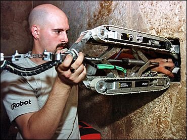
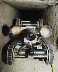 Pyramid Rover being deployed (left) and inside the square tunnel (right)
Robot explorers have indeed been playing very important role in other archeological expeditions, helping archeologists unearth ‘lost’ civilizations and solve the underlying ancient mysteries buried underground. So popular the participation of robots in these projects, scientists have come up with a branch of engineering specializing in this area, called “Ancient Engineering”. Who knows what robots may discover next time...
Da Vinci - Robotic Assisted, Minimally Invasive Cardiac Surgery
Minimally Invasive Surgical (MIS) procedures have been brought to a new level of advancement with the existence of Da Vinci Surgical system, in which the system combines robotics and computer technology to allow surgeons to perform delicate surgical procedures. By making use of these surgical robots, human surgeons can fully manipulate small instruments, which are inserted through small chest incisions, in tight spaces, thus achieving most of those technical maneuvers that are only made possible with open exposure. Nowadays, hospital have begun to utilize this technology, and are currently involved in several exciting clinical protocols testing this surgical system, manufactured by Intuitive Surgical, Inc. (Mountainview, CA) for a variety of cardiac surgical operations.
Technology behind Da Vinci Surgical System
 The system consists of three main components: the surgeon’s viewing and control console, the surgical cart, which consists of the robotic arm that can position and maneuver detachable surgical EndoWrist instruments, and the video tower that consists of the video camera and processing units.
The pencil sized instruments which are attached to the robotics arms, together with computer enhanced mechanical wrists are being designed for the purpose of providing dexterity movements of the human surgeon’s forearm and wrist during operation site through entry ports which are less than 1 cm. Thus, with the precision and accuracy of surgical movements, it allows surgeon to enter the chest through keyhole incisions and performed closed chest, heart and lung surgery. The robot’s mechanical wrists can bend forth and backward, side to side, and rotate in a full circular motion, while holding the surgical tools, thus it provides a greater range of motion than which is not made possible with human beings. The wrists imitate the motions which are made by the surgeon who sits at the console outside the operation room. He will monitor the whole surgical operation through an eyepiece that provides high resolution, multi color, magnified and three dimension images of the surgical site which is provided by the endoscope. The surgeon will move along his hands which are attached to the controls of the robotic system, and the robotic hands will follow. The built in computer for this system will enhance the surgeon's hand movement with more precision and less tremors which is considered an important factor in performing successful delicate bypass and valve surgery.
Potential Impact of Da Vinci Surgical Technology
This robotic surgery technology has the potential to impact the practice of cardiac surgery in many ways. It allows the existing MIS operations to be made more easily and routine. These surgical procedures which are performed by using MIS techniques can be performed more quickly and easily with the increased dexterity and control provided by robotic assistance. On the other hand, those surgical procedures that today are performed only rarely using MIS techniques can be achieved routinely with robotic assistance. Some of the surgical procedures have been adapted for port-based techniques but the problem is that it is extremely difficult to perform and only currently is being done by a limited number of highly skilled surgeons. Now, with this availability of robotic assistance, more surgeons at more institutions will be able to perform these procedures. It also makes new surgical procedures possible as a certain number of procedures that are currently not feasible by MIS techniques may eventually be performed through small incisions with the help of robotic technology. Thus, only small incisions are needed for the small dedicated robotic arms to perform the operation, reducing the invasive nature of the operations and the risk of other complications arising from it.
Future of Da Vinci Surgical Technology
The future will be even brighter with the existence of this technology. If operations can be made by a surgeon from across a room, one would suppose that the operation could be made from another room or even from another country. It means that a doctor could even perform surgery from his own home with the existence of this technology. The implications for this technology include the possibility of operating on residents of a remote village who do not have the access to a specialized surgeon, or during war when a wounded soldier could be taken into an army vehicle equipped with the robotic system while the surgeon may operate from one safe location in an efficient manner on many wounded soldiers. Even astronauts can be operated on by these robots in the outer space!!! Hope this blog can give you all guys a clearer picture of the existing robotic surgery technology.
References
[1] http://www.uchospitals.edu/specialties/minisurgery/benefits/davinci.html
[2] http://www.shawneemission.org/content/view/61/112/
[3] http://library.thinkquest.org/C0126120/telesurgery.htm
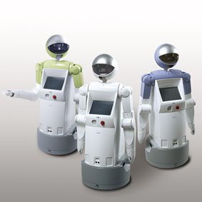
Enon -- Fujitsu's Service Robot
 Introduction
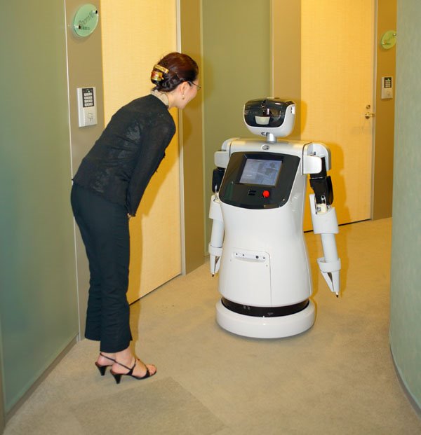
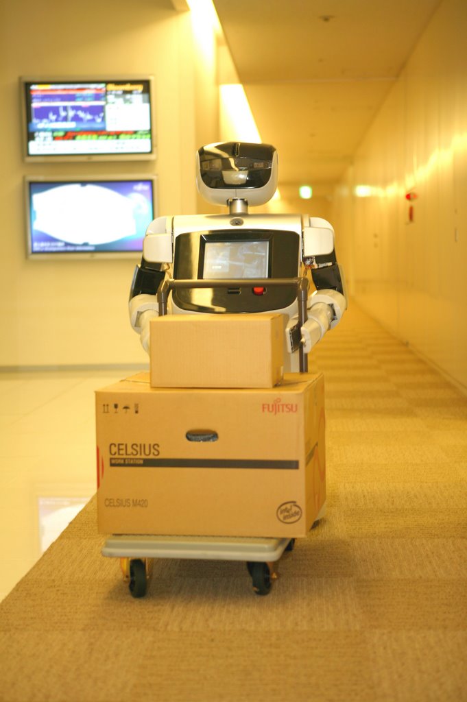
The Fujitsu Enon Robot was designed to provide support for various services in offices, commercial facilities, and other public areas in which people work or spend leisure time. The newly developed robot features functions that enable it to provide such services as greeting and escorting guests onto elevators, operating the elevators, moving parcels using a cart, and security patrolling of buildings at night.
Introduction
The Fujitsu Enon Robot was designed to provide support for various services in offices, commercial facilities, and other public areas in which people work or spend leisure time. The newly developed robot features functions that enable it to provide such services as greeting and escorting guests onto elevators, operating the elevators, moving parcels using a cart, and security patrolling of buildings at night.
 In fact, it is actually going into service at the Yachiyo location of Japanese supermarket chain Aeon. According to Digital World Tokyo, Enon will be helping Aeon customers with everything from packing shopping bags and picking up groceries to find their way around the store.
Not only can the Enon robot help customers in the supermarket, it can serve as a butler as well. Fetching you stuff and patrolling your pad like a security guard when you're out or tucked up in bed, it even hooks up to your home network via Wi-Fi. This wireless set-up enables you to access files from your PC or browse the web using the touchsceen LCD screen embedded in its belly, regardless of where you are in your home
Enon is an acronym of the phrase "exciting nova on network." The phrase conveys the robot's ability to autonomously support customers' tasks while being linked to a network.
In fact, it is actually going into service at the Yachiyo location of Japanese supermarket chain Aeon. According to Digital World Tokyo, Enon will be helping Aeon customers with everything from packing shopping bags and picking up groceries to find their way around the store.
Not only can the Enon robot help customers in the supermarket, it can serve as a butler as well. Fetching you stuff and patrolling your pad like a security guard when you're out or tucked up in bed, it even hooks up to your home network via Wi-Fi. This wireless set-up enables you to access files from your PC or browse the web using the touchsceen LCD screen embedded in its belly, regardless of where you are in your home
Enon is an acronym of the phrase "exciting nova on network." The phrase conveys the robot's ability to autonomously support customers' tasks while being linked to a network.
 The new service robot is comprised of a head capable of moving up, down, left, and right, arms with four degrees of freedom, left and right motor-driven wheels that can rotate independently, a CPU that controls the entire robot, and a 3D visual processing system comprised of a digital signal processor (DSP) and custom hardware.
Applications
The following are three applications of the Enon Robot:
1. Guidance and escorting
Enon is suited for reception duties or explaining of exhibits, as it can detect when people stand in front of it and can provide a variety resourceful information such as product details, in addition to escorting guests to designations. Aside from its voice function, through its touch panel LCD monitor, Enon can also offer a multitude of user-friendly information through visual images. This monitor can also be utilized to administer questionnaires and through interconnection to a server can be used to accumulate guest information.
The new service robot is comprised of a head capable of moving up, down, left, and right, arms with four degrees of freedom, left and right motor-driven wheels that can rotate independently, a CPU that controls the entire robot, and a 3D visual processing system comprised of a digital signal processor (DSP) and custom hardware.
Applications
The following are three applications of the Enon Robot:
1. Guidance and escorting
Enon is suited for reception duties or explaining of exhibits, as it can detect when people stand in front of it and can provide a variety resourceful information such as product details, in addition to escorting guests to designations. Aside from its voice function, through its touch panel LCD monitor, Enon can also offer a multitude of user-friendly information through visual images. This monitor can also be utilized to administer questionnaires and through interconnection to a server can be used to accumulate guest information.
 2. Transport of objects
Enon can carry parcels an internal storage compartment in its torso and deliver them to a designated location. Through network interconnection, users can call for Enon to come from a remote location and have goods delivered to a specified designation.
3. Security patrolling
Enon is capable of regularly patrolling facilities following a pre-set route, and by using a network has the ability to transmit images of stipulated locations to a remote surveillance station. Enon can also respond flexibly or to users' spontaneous requests through a network, such as directing enon to view specific sites.
Features
1. Autonomous navigation enabling easy operation
By referring to a pre-programmed map, using its wide-angle cameras on its head to perceive the presence of people or objects surrounding itself while simultaneously determining their location, Enon can autonomously move to a designated location while avoiding obstacles. This makes Enon extremely user-friendly in that there is no need for special markings to be placed on floors or walls of the robot’s route as guides.
2. Transport of objects
Enon can carry a maximum load of 10 kilograms in the internal storage compartment of its torso and safely deliver to a designated location. By using its specially designed carriage, Enon can unload objects as well.
3. Handling of objects
With a single arm, Enon is capable of grasping and passing objects that are up to 0.5 kilograms. Compared to the four degrees of freedom which the arms of its prototype featured, Enon's arm features have been enhanced to enable five degrees of freedom.
4. Feature-rich communication functions
Speech recognition and speech synthesis in Japanese are included as standard features. Enon's touch panel LCD monitor on its chest enables the robot to communicate in a diverse range of situations.
5. Linkable to networks
By linking Enon to a network through a wireless LAN, it can offer a variety of functions such as retrieving necessary information from a server and providing the information either by voice or image, or transmitting images self-accumulated by the robot to the server. Fujitsu plans to provide external control and remote control functions as options.
6. Swivel-head feature enables facing reverse directions
When providing information to users, Enon operates with its head and arms facing the same side as its touch panel LCD monitor, so that Enon faces its users. When relocating itself from one location to another or when carrying objects that are stored in the carriage of its torso, Enon's head and arms swivel to face the same direction it is moving toward, which is reverse the side featuring its LCD monitor. This enables Enon to continue to communicate through its LCD monitor with users located behind itself, even while it is relocating. Enon can also autonomously maintain a natural posture, by keeping the same range of arm motion when providing information and while relocating.
7. Wide variety of expressions
Light emitting diodes (LEDs) on the eye and mouth area of its face enable enon to have a wide range of facial expressions. Enon also has LEDs on the back of its head, making it possible for the robot to display its operational state to the rear as well.
8. Safety
Fujitsu has placed utmost priority on making Enon safe, incorporating a variety of safety features including significantly reducing the weight and width of the robot compared to its prototype, and enhancing arm functions. Enon is currently undergoing safety appraisal (appraisal in process) by an external third party, the NPO Safety Engineering Laboratory. Fujitsu will continue to place utmost importance on safety of its products.
Links
http://www.fujitsu.com/global/news/pr/archives/month/2005/20050913-01.html
http://www.fujitsu.com/global/news/pr/archives/month/2004/20040913-01.html
2. Transport of objects
Enon can carry parcels an internal storage compartment in its torso and deliver them to a designated location. Through network interconnection, users can call for Enon to come from a remote location and have goods delivered to a specified designation.
3. Security patrolling
Enon is capable of regularly patrolling facilities following a pre-set route, and by using a network has the ability to transmit images of stipulated locations to a remote surveillance station. Enon can also respond flexibly or to users' spontaneous requests through a network, such as directing enon to view specific sites.
Features
1. Autonomous navigation enabling easy operation
By referring to a pre-programmed map, using its wide-angle cameras on its head to perceive the presence of people or objects surrounding itself while simultaneously determining their location, Enon can autonomously move to a designated location while avoiding obstacles. This makes Enon extremely user-friendly in that there is no need for special markings to be placed on floors or walls of the robot’s route as guides.
2. Transport of objects
Enon can carry a maximum load of 10 kilograms in the internal storage compartment of its torso and safely deliver to a designated location. By using its specially designed carriage, Enon can unload objects as well.
3. Handling of objects
With a single arm, Enon is capable of grasping and passing objects that are up to 0.5 kilograms. Compared to the four degrees of freedom which the arms of its prototype featured, Enon's arm features have been enhanced to enable five degrees of freedom.
4. Feature-rich communication functions
Speech recognition and speech synthesis in Japanese are included as standard features. Enon's touch panel LCD monitor on its chest enables the robot to communicate in a diverse range of situations.
5. Linkable to networks
By linking Enon to a network through a wireless LAN, it can offer a variety of functions such as retrieving necessary information from a server and providing the information either by voice or image, or transmitting images self-accumulated by the robot to the server. Fujitsu plans to provide external control and remote control functions as options.
6. Swivel-head feature enables facing reverse directions
When providing information to users, Enon operates with its head and arms facing the same side as its touch panel LCD monitor, so that Enon faces its users. When relocating itself from one location to another or when carrying objects that are stored in the carriage of its torso, Enon's head and arms swivel to face the same direction it is moving toward, which is reverse the side featuring its LCD monitor. This enables Enon to continue to communicate through its LCD monitor with users located behind itself, even while it is relocating. Enon can also autonomously maintain a natural posture, by keeping the same range of arm motion when providing information and while relocating.
7. Wide variety of expressions
Light emitting diodes (LEDs) on the eye and mouth area of its face enable enon to have a wide range of facial expressions. Enon also has LEDs on the back of its head, making it possible for the robot to display its operational state to the rear as well.
8. Safety
Fujitsu has placed utmost priority on making Enon safe, incorporating a variety of safety features including significantly reducing the weight and width of the robot compared to its prototype, and enhancing arm functions. Enon is currently undergoing safety appraisal (appraisal in process) by an external third party, the NPO Safety Engineering Laboratory. Fujitsu will continue to place utmost importance on safety of its products.
Links
http://www.fujitsu.com/global/news/pr/archives/month/2005/20050913-01.html
http://www.fujitsu.com/global/news/pr/archives/month/2004/20040913-01.html
Underwater, Unmanned, Untethered - A new paradigm in undersea surveillance
Introduction Before the advent of the Advanced Unmanned Search System (AUSS), researchers faced a tradeoff between using tethered and untethered undersea surveillance robots. The untethered robots obviously had more freedom and range of movement, without chances of wires getting caught or tangled, but they lacked the capability of transmitting real-time information to the user. Furthermore, an untethered vehicle can move at relatively high speeds and perform sharp, precise maneuvers, or it can hover stably without expending power fighting cable pull. The AUSS, developed by Richard Uhrich & James Walton at the Naval Command, Control and Ocean Surveillance Center of SPAWAR Systems Center in San Diego, is an underwater vehicle which is both unmanned and untethered. Communication with a surface ship is accomplished by means of underwater sound, by means of a sophisticated digital acoustic link. Its operation is similar to that of a space probe, with the robot proceeding on its own, and able to receive real-time instructions at any time. Advanced abilities of the AUSS include going to a newly commanded location, hovering at a specified altitude and location, executing a complete search pattern, or returning home on command.
Purpose
The purpose of AUSS is to improve the Navy's capability to locate, identify and inspect objects on the bottom of the ocean up to depths to 20,000 feet. The vehicle utilizes sophisticated search sensors, computers, and software, and it is self-navigating. When commanded to do so, it can autonomously execute a predefined search pattern at high speed, while continuously transmitting compressed side-looking sonar images to the surface. The operators evaluate the images and supervise the operation. If they wish to further check out a certain object, they can order the vehicle to temporarily suspend sonar search and swim over for a closer look using its scanning sonar or still-frame electronic camera. Each camera image is also compressed and transmitted to the surface. If the operators see that the contact is not the object sought, a single command causes the vehicle to resume the search from where it left off.
Once the object sought is recognized, a detailed optical inspection can be conducted immediately. The AUSS offers multiple options for this, including:
- Previously transmitted images can be retransmitted at higher resolution.
- New optical images can be requested from different altitudes and positions.
- A documentary film camera can be turned on or off.
- If the object of interest is very large or found to be highly fragmented, the vehicle can perform a small photomosaic search pattern, taking overlapping pictures guaranteeing total optical coverage of a defined area.
How Acoustic Communication Works
As opposed to physical cables like fibre-optic cables, the AUSS communicates via sound. The acoustic link transmits compressed search data to the surface at rates up to 4800 bits per second, and sends high level commands to the vehicle at 1200 bits per second. Given the robot vehicle’s intelligence, the operator does not have to supervise it at each step. Instead, higher level commands of what to do (rather than how to do it) are given. The AUSS autonomously performs each task until it is completed or until the operators interrupt with a new command.
Navigation
The vehicle's computers use a Doppler sonar and a gyrocompass to perform onboard navigation.
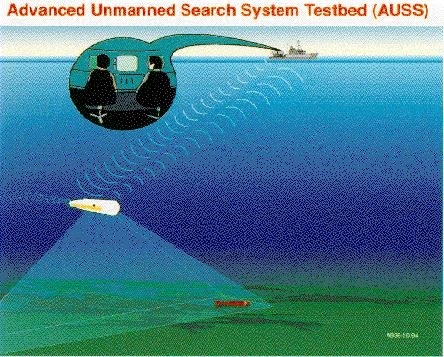 Control
Generally, all critical loops on the robot’s control system are closed. This means that the operator does not have to employ joystick-like control of every movement. The intelligence and navigation of the AUSS allows the user to instruct it to move to a specified location, say a few miles away, and have the confidence that it will successfully navigate itself to that location without further input.
On the other hand, the operator has the freedom to give new instructions or interrupt some decision loop that is executing on the robot. This frees the AUSS from being limited to pre-programmed routines and allows the operator to apply his intelligence and experience to control the robot vehicle. Since images are fed back to the operator constantly, once there is something interesting the operator can instruct the AUSS to make closer investigation, in the variety of ways outlined above.
Image sensors
There are two ways of relaying search information back to the human operator – sonar and optical images. Sonar images can be generated faster and have a very large range, but the resolution is poor. Optical images, on the other hand, are taken at the range of a few feet and offer greater detail. Generally, if a human wants to take a closer look at any object, an optical image is necessary to confirm the status of the object.
Other specifications
The AUSS vehicle is designed to operate as deep as 20,000 feet. It is 17 feet long, 31 inches in diameter, and weighs 2800 pounds. The center section is a cylindrical graphite epoxy pressure hull with titanium hemispherical ends. The hull provides the central structure and all its buoyancy---no syntactic foam is used. The free-flooded forward and aft end fairings and structure are of Spectra, a nearly buoyant composite.
At its maximum speed of five knots, the endurance of the AUSS silver-zinc batteries is ten hours. Recharging requires 20 hours. Typical missions have been ten to fifteen hours. Three sets of batteries would allow AUSS to operate indefinitely, with only 3-1/2 hours between 20,000 foot dives.
Control
Generally, all critical loops on the robot’s control system are closed. This means that the operator does not have to employ joystick-like control of every movement. The intelligence and navigation of the AUSS allows the user to instruct it to move to a specified location, say a few miles away, and have the confidence that it will successfully navigate itself to that location without further input.
On the other hand, the operator has the freedom to give new instructions or interrupt some decision loop that is executing on the robot. This frees the AUSS from being limited to pre-programmed routines and allows the operator to apply his intelligence and experience to control the robot vehicle. Since images are fed back to the operator constantly, once there is something interesting the operator can instruct the AUSS to make closer investigation, in the variety of ways outlined above.
Image sensors
There are two ways of relaying search information back to the human operator – sonar and optical images. Sonar images can be generated faster and have a very large range, but the resolution is poor. Optical images, on the other hand, are taken at the range of a few feet and offer greater detail. Generally, if a human wants to take a closer look at any object, an optical image is necessary to confirm the status of the object.
Other specifications
The AUSS vehicle is designed to operate as deep as 20,000 feet. It is 17 feet long, 31 inches in diameter, and weighs 2800 pounds. The center section is a cylindrical graphite epoxy pressure hull with titanium hemispherical ends. The hull provides the central structure and all its buoyancy---no syntactic foam is used. The free-flooded forward and aft end fairings and structure are of Spectra, a nearly buoyant composite.
At its maximum speed of five knots, the endurance of the AUSS silver-zinc batteries is ten hours. Recharging requires 20 hours. Typical missions have been ten to fifteen hours. Three sets of batteries would allow AUSS to operate indefinitely, with only 3-1/2 hours between 20,000 foot dives.
 Test results
In the summer of 1992 the system performed a series of sea tests off San Diego culminating in a 12,000 foot operation. AUSS conducted side looking sonar search at five knots, and performed detailed optical inspections of several objects which it found. It proved capable of sustained search rates approaching a square nautical mile per hour, including the time spent investigating false targets. The image shows a World War II Dauntless Dive Bomber identified by the AUSS.
Test results
In the summer of 1992 the system performed a series of sea tests off San Diego culminating in a 12,000 foot operation. AUSS conducted side looking sonar search at five knots, and performed detailed optical inspections of several objects which it found. It proved capable of sustained search rates approaching a square nautical mile per hour, including the time spent investigating false targets. The image shows a World War II Dauntless Dive Bomber identified by the AUSS.
Issues At this point, I will raise some issues for consideration. Here, unmanned vehicle means that low-level instructions on navigating and doing pre-programmed search are unnecessary. However, the AUSS still requires human supervision to detect unique objects, and to decide which objects to further investigate. This may result in problems in missions where there has to be acoustic silence, or where manpower is insufficient. Can a better algorithm and control system be developed such that the AUSS be equipped with sufficient intelligence to discern between interesting and trivial objects? Also, given the kind of technology that the navy employs in such robots for undersea surveillance, could such vehicles also be used for scientific research and oceanography at the same time? The deep oceans are still relatively unexplored and the information returned by such robots could prove invaluable to the scientific community and mankind in turn. Reference links:
Patients - Simulated
We’ve seen many of the wonderful ways in which robots can be used in the medical arena; from patient rehabilitation to telesurgery, robots have truly been of aid to patients and doctors alike. While we rejoice over technological advances made in the field of medical robotics, let us not forget one more group of people in the medical world that robots can help – the doctors and surgeons-to-be!
Yup, that’s right, even doctors and surgeons-in-training will find robots useful to them. How so? The Laerdal SimMan offers an answer: a robot for trainees to practise on.
Gone are the days when trainees have to rely on lifeless mannequins to carry out Cardiopulmonary Resuscitation (CPR), or actual patients to carry out Advanced Cardiac Life Support (ACLS), Advanced Trauma Life Support (ATLS) or even anaesthesia administration; mannequins are certainly poor training tools as compared to actual patients, but there definitely aren’t any ‘spare’ patients that can be used for ‘redoing’ either! The SimMan, dubbed the ‘Universal Patient Simulator’ offers trainees the interactivity ordinary mannequins cannot provide. It is a medical robot specially designed with a plethora of features to simulate many behaviours of a patient.
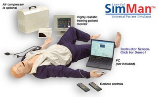 The SimMan looks, feels and acts very much like a patient. Its features are simply too numerous to count; some of these include realistic airway features with spontaneous respiration, variable respiratory rate and airway complications such as pharyngeal obstruction, tongue oedema, trismus, laryngospasm, decreased cervical range of motion, decreased lung compliance, stomach distension, pneumothorax decompression, cardiac functions with an ECG library of over 2,500 cardiac rhythm variants, CPR functions, pulse and blood pressure functions, circulatory and IV drug administration features, simulated patient sounds, as well as convenient interfacing with computers and software for control and logging. In short, SimMan provides trainees with an opportunity for extremely realistic, hands-on practice that could be carried out again and again. One of the best things is perhaps that of the simulated patient sounds; not only are the moans and groans a good indication of something being done wrongly, they are probably something the trainees will have to get themselves used to in the future.
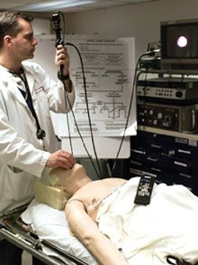 The SimMan is one of 2 robot patient simulators that Laerdal has to offer; the AirMan is the other. The AirMan serves as a simulator for the more specific field of difficult airway management, and includes airway features, CPR, pulse and blood pressure features, circulatory and IV drug administration features as well as simulated patient sounds.
A little bit of history on the invention of robot patients here: In 1979, René Gonzalez, one of the inventors of SimMan witnessed a crew rushing to tend to an asphyxiating patient, albeit unsuccessfully, and wondered if things could be done better. He realised that there were too few avenues for real-life emergency handling practice, and the existing simulators available for medical trainees were expensive and not realistic enough. Hence, in 1995, he and a friend created ADAM (acronym for Advanced Difficult Airway Management), which was a life-sized, anatomically correct, 70-pound robot. ADAM breathed, talked, coughed, vomited, moaned, cried, had a pulse and measurable blood pressure, reacted to IV drugs and other treatments and could be remote controlled. It was from ADAM that SimMan and AirMan were evolved.
All in all, both the robots SimMan and AirMan serve as a great alternative for medical trainees to practise their skills on. The not-too-forbidding price tag of US$10,000 to US$25,000 per unit helps as well.
The SimMan is one of 2 robot patient simulators that Laerdal has to offer; the AirMan is the other. The AirMan serves as a simulator for the more specific field of difficult airway management, and includes airway features, CPR, pulse and blood pressure features, circulatory and IV drug administration features as well as simulated patient sounds.
A little bit of history on the invention of robot patients here: In 1979, René Gonzalez, one of the inventors of SimMan witnessed a crew rushing to tend to an asphyxiating patient, albeit unsuccessfully, and wondered if things could be done better. He realised that there were too few avenues for real-life emergency handling practice, and the existing simulators available for medical trainees were expensive and not realistic enough. Hence, in 1995, he and a friend created ADAM (acronym for Advanced Difficult Airway Management), which was a life-sized, anatomically correct, 70-pound robot. ADAM breathed, talked, coughed, vomited, moaned, cried, had a pulse and measurable blood pressure, reacted to IV drugs and other treatments and could be remote controlled. It was from ADAM that SimMan and AirMan were evolved.
All in all, both the robots SimMan and AirMan serve as a great alternative for medical trainees to practise their skills on. The not-too-forbidding price tag of US$10,000 to US$25,000 per unit helps as well.
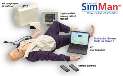 The SimMan looks, feels and acts very much like a patient. Its features are simply too numerous to count; some of these include realistic airway features with spontaneous respiration, variable respiratory rate and airway complications such as pharyngeal obstruction, tongue oedema, trismus, laryngospasm, decreased cervical range of motion, decreased lung compliance, stomach distension, pneumothorax decompression, cardiac functions with an ECG library of over 2,500 cardiac rhythm variants, CPR functions, pulse and blood pressure functions, circulatory and IV drug administration features, simulated patient sounds, as well as convenient interfacing with computers and software for control and logging. In short, SimMan provides trainees with an opportunity for extremely realistic, hands-on practice that could be carried out again and again. One of the best things is perhaps that of the simulated patient sounds; not only are the moans and groans a good indication of something being done wrongly, they are probably something the trainees will have to get themselves used to in the future.
 The SimMan is one of 2 robot patient simulators that Laerdal has to offer; the AirMan is the other. The AirMan serves as a simulator for the more specific field of difficult airway management, and includes airway features, CPR, pulse and blood pressure features, circulatory and IV drug administration features as well as simulated patient sounds.
A little bit of history on the invention of robot patients here: In 1979, René Gonzalez, one of the inventors of SimMan witnessed a crew rushing to tend to an asphyxiating patient, albeit unsuccessfully, and wondered if things could be done better. He realised that there were too few avenues for real-life emergency handling practice, and the existing simulators available for medical trainees were expensive and not realistic enough. Hence, in 1995, he and a friend created ADAM (acronym for Advanced Difficult Airway Management), which was a life-sized, anatomically correct, 70-pound robot. ADAM breathed, talked, coughed, vomited, moaned, cried, had a pulse and measurable blood pressure, reacted to IV drugs and other treatments and could be remote controlled. It was from ADAM that SimMan and AirMan were evolved.
All in all, both the robots SimMan and AirMan serve as a great alternative for medical trainees to practise their skills on. The not-too-forbidding price tag of US$10,000 to US$25,000 per unit helps as well.
The SimMan is one of 2 robot patient simulators that Laerdal has to offer; the AirMan is the other. The AirMan serves as a simulator for the more specific field of difficult airway management, and includes airway features, CPR, pulse and blood pressure features, circulatory and IV drug administration features as well as simulated patient sounds.
A little bit of history on the invention of robot patients here: In 1979, René Gonzalez, one of the inventors of SimMan witnessed a crew rushing to tend to an asphyxiating patient, albeit unsuccessfully, and wondered if things could be done better. He realised that there were too few avenues for real-life emergency handling practice, and the existing simulators available for medical trainees were expensive and not realistic enough. Hence, in 1995, he and a friend created ADAM (acronym for Advanced Difficult Airway Management), which was a life-sized, anatomically correct, 70-pound robot. ADAM breathed, talked, coughed, vomited, moaned, cried, had a pulse and measurable blood pressure, reacted to IV drugs and other treatments and could be remote controlled. It was from ADAM that SimMan and AirMan were evolved.
All in all, both the robots SimMan and AirMan serve as a great alternative for medical trainees to practise their skills on. The not-too-forbidding price tag of US$10,000 to US$25,000 per unit helps as well.Reference Links:
Friday, April 07, 2006
In future a traffic jam can be more than just time-consuming ...
We all know the situation. The flow of traffic is becoming slower, jamming and after a (long) while you can see the reason for your delay. Several signs and traffic cones are blocking at least one of the lanes, since an accident happened or the road is is beeing repaired.
 Placing these signs and cones is often very dangerous for the workers and takes a lot of time, since the task has to be done consecutively.
To accelerate this process, minimize the working zone, increase the safety of every road user and save money (in terms of lost productivity) Dr. Shane Farritor and his team from the Mechanical Engineering Department at the University of Nebraska-Lincoln animated the normally lifeless safety barrels (brightly colored, 130cm high, 50cm in diameter) as the first elements of a team of Robotic Safety Markers (RSM) that will include signs, cones and possibly barricades and arrestors.
Each of these Robotic Safety Barrels (RSB) has two wheels which are independently driven by two motors. Such a system of barrels consists of a lead robot and the deployed RSMs. The lead robot, which can be a maintenance vehicle, is equipped with sensors and complex computational and communication resources to globally locate and control the RSBs (deliberative control). It locates them using a laser range finder and identifies them with help of a Hough transformation algorithm.
To set the barrel’s positions the user (in the maintenance vehicle) places them by clicking on the locations in a video image of the roadway. Since normal roadways are relatively easy to predict, the primary obstacles for the RSBs are other barrels.
To calculate the desired paths, a parabolic polynomial is used to compute the waypoints for the RSBs, which are sent to them. From this moment on the barrels try to find their way to this waypoint (reactive control).
This is done by an microcontroller, running with a realtime operating system (µC/OS-II) and a PID-Controller which uses kinematic relationships between wheel velocities and coordinates to calculate path-corrections.
An example can be found in [2].
The first tests with 5 Barrels were succesful and the maximum deviation from the path and final positions was within the requirements for barrel placement and even exceeded the accuracy of current human deployment. Eventually it is probably just a matter of time until we can see this new invention on our streets.
References:
[1]http://robots.unl.edu/projects/index.html
[2]http://robots.unl.edu/files/papers2/IEEE_Intelligent_Systems_Nov.Dec2004.pdf
[3]http://www.scienceticker.info/news/EplFkFZylueYfhTGPv.shtml
Placing these signs and cones is often very dangerous for the workers and takes a lot of time, since the task has to be done consecutively.
To accelerate this process, minimize the working zone, increase the safety of every road user and save money (in terms of lost productivity) Dr. Shane Farritor and his team from the Mechanical Engineering Department at the University of Nebraska-Lincoln animated the normally lifeless safety barrels (brightly colored, 130cm high, 50cm in diameter) as the first elements of a team of Robotic Safety Markers (RSM) that will include signs, cones and possibly barricades and arrestors.
Each of these Robotic Safety Barrels (RSB) has two wheels which are independently driven by two motors. Such a system of barrels consists of a lead robot and the deployed RSMs. The lead robot, which can be a maintenance vehicle, is equipped with sensors and complex computational and communication resources to globally locate and control the RSBs (deliberative control). It locates them using a laser range finder and identifies them with help of a Hough transformation algorithm.
To set the barrel’s positions the user (in the maintenance vehicle) places them by clicking on the locations in a video image of the roadway. Since normal roadways are relatively easy to predict, the primary obstacles for the RSBs are other barrels.
To calculate the desired paths, a parabolic polynomial is used to compute the waypoints for the RSBs, which are sent to them. From this moment on the barrels try to find their way to this waypoint (reactive control).
This is done by an microcontroller, running with a realtime operating system (µC/OS-II) and a PID-Controller which uses kinematic relationships between wheel velocities and coordinates to calculate path-corrections.
An example can be found in [2].
The first tests with 5 Barrels were succesful and the maximum deviation from the path and final positions was within the requirements for barrel placement and even exceeded the accuracy of current human deployment. Eventually it is probably just a matter of time until we can see this new invention on our streets.
References:
[1]http://robots.unl.edu/projects/index.html
[2]http://robots.unl.edu/files/papers2/IEEE_Intelligent_Systems_Nov.Dec2004.pdf
[3]http://www.scienceticker.info/news/EplFkFZylueYfhTGPv.shtml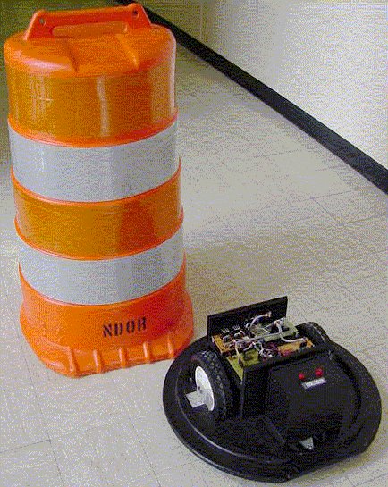
Robolobster - Military tools for land and sea operations
Have you all guys ever seen a robot that looks like a lobster? In fact, unknown to many people, the most amazing capability of a lobster is that they have a very sharp sense of smell, which they used to detect and trace the odor of their food to its source in the turbulent conditions of the ocean. Recently, scientists have been working in a new field which is known as biomemetic robots. They believe that we, as human beings can solve real world problems by dissecting this and other forms of animal intelligence and use this kind of knowledge to design and program autonomous machines with similar superhuman capabilities. Such kind of robots can explore the ocean bed and track underwater sources of pollution, detect and locate mines and other unexploded ordances, e.t.c.
 Thus, this blog gives an opportunity to do an introduction and know more about the operation of biomimetic underwater robots, Robolobster at Northeastern University, Marine science centre at Nahant, Mass. These robots are being designed and built in a way that they resemble and behave like a real lobster. In fact, it is important to take note that these robots are able to take advantage of capabilities proven in animals,i.e lobsters for dealing with real-world environments. This is a US Navy research project and the military organization are making use of the versatility of the robot’s operation on both water and land for conduction of mine detection, rescue and search operations in different kinds of enviroments.
Fig 1: A picture of Robolobster
Feature and technology of the Robolobster
The robot has a body size of an 8” by 5” hull , width of about two feet long, has eight legs and weight about seven pounds on land.
It is found out that these underwater robots are more negatively buoyant compared to real underwater animals, therefore the robots will have a higher chance of experience a surge in the underwater and try to move around at the bottom due to its light weight. The eight legs of the robot thus provide an advantage of more traction to gain a higher mobility in these kinds of situations.
The robot has dedicated artificial muscles which are responsible for its leg movement, which is made of a nickel-titanium alloy called nitinol. This material will contract when electricity is applied and expands, thus it has a certain degree of resemblance to real muscles involved. Thus, the mobility of the underwater robots is being made easier in this kind of architecture.
The main power source of the robot comes from a rechargeable NiMH or lithium ion polymer battery pack and it will be controlled by a neuronal-circuit based controller. The function of this controller is to carry out a set of behavioral actions which mimics the motion of lobsters adapting to the environment in which they carry out their target search movement. One example is that lobsters will wiggle and squirm in order to get out of a stuck spot. Thus, the controller will incorporate a variable level of chaos in its own circuitry so that the robots will generate locomotion such that the locomotoring pattern will have own variations, which constitute the wiggling and squirming that enables the robots to get out of stuck spots.
The RoboLobster will have sensors that would detect metal, chemicals and explosive objects of other underwater vehicles during their land and underwater operation. A video camera has been used before in the prototype testing and has been proved to be successful but the limitation of this capability is that its effectiveness depends on the availability of the light.
Deployment of Robolobster
The deployment of Robolobster is carried out in a few certain ways. The first approach is to release four to five robots in a designated area. Each of these robots will be programmed to explore the area in a random manner, whenever it detects an unknown object, it would transmit the information in form of RF wave signals to military personnel on the surface. The robot will be rigged with a small explosive charge and the personnel can signal it to detonate the mine.

Fig 2: Robolobster movement in underwater
During the deployment, each of these robots will be placed with a sonar marker to delineate a particular area for them to explore. The purpose is to let each robot communicate with each other so that one can signal to another that they has crossed an invisible boundary and should stay away from it. Upon completing their search mission, they are signaled to gather at a certain location where they can be retrieved or proceed to the mode of self destruction. In conclusion, the RoboLobster are considered autonomous machine in the sense that their legs are equppied with preprogrammed sensors that will prohibit them from moving when it encounters an object. However, they are not fully considered autonomous because the command to self-detonate, for example, would most likely come from military personnel.
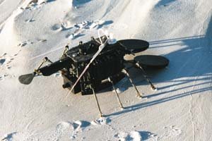
Hope you all enjoy this interesting blog!!!

Fig 3: Robolobster movement on land
Subscribe to:
Comments (Atom)